
Rongqing Dai
Abstract
The notion of Flying Saucer has been closely related to Extraterrestrials for many decades; however, the fact that we Homo sapiens have already mastered the necessary technologies to build Flying Saucers has been long ignored. Although ETs from another planet could be very realistic, it does not necessarily entail the conclusion that Flying Saucers in our sky must all be flown by aliens. In this article, we will explore the feasibility of building an ET style Flying Saucer with the conventional technologies that have become part of the popular science. The most critical challenges for building a functional Flying Saucer will be covered in this article. In this way, we could convince the public that humans have been able to build a Flying Saucer since decades ago, which could help to philosophically clarify the popular myth that the so-called UFOs in the sky are all flown by aliens.
Keywords Flying Saucer, Plasma, High Voltage, Reactor, ET, UFO
Introduction
The populace of this world has been baffled by the myth of the Flying-Saucer-related Unidentified Flying Objects for quite a long time. The central theme of all the Flying Saucer reports is the so-called extraterrestrial aliens. However, while ETs from other parts of the universe could be very realistic, it does not necessarily entail the conclusion that those swift and glowing Flying Saucers must all be driven by aliens. As is demonstrated in this writing, humans have already mastered the necessary knowledge and technologies to build a glowing Flying Saucer which could not only fly super swiftly but also change its flying direction abruptly. Accordingly, a Flying Saucer with visitors from a foreign country instead of a foreign planet could be very realistic as well.
Typically, the sighting reports of Flying Saucers often come with emotional exclamations like “it’s impossible for humans to do this”, “it’s definitely not human because I don’t believe we have this kind of technology”. While those remarks would be soundly correct if referring to reports of UFO events happened early last century or before, they might be challengeable when referring to reports after 1970s. This is because humans had learned some knowledge and technologies that are fundamental for building a Flying Saucer for quite a while at that time.
Philosophically speaking, if we can demonstrate the feasibility of building a UFO style Flying Saucer with our known technologies that have been available for decades, then our demonstration could very well serve to invalidate the implicit logical premise for the above mentioned remarks. In order to do so, let’s first look at what have been considered as the basic characteristics of the UFO style Flying Saucers.
Flying Saucers As We Know
There have been thousands of Flying Saucer sighting reports for the past many decades. Although the locations of the sightings disperse from outer space to the most remote corners of the world, across a time span of tens of thousands of days, those eyewitnesses, from astronauts in spaceships, to aircraft pilots and passengers, to ground observers, have all depicted very similar pictures of the Flying Saucers, which could be roughly summarized as follows:
First, Flying Saucers all take the shape of saucer that is supposed to be hydrodynamically inefficient due to its high resistance to air flow, but they fly super fast;
Second, they have neither rotor blades nor jet engines;
Third, they are often reported as glowing;
Fourth, they could make sudden stops, sudden vertical movements, or sudden changes of flying direction;
Fifth, their sizes are normally huge;
Sixth, sometimes when they are seen by eyes, they do not appear on the radar;
Seventh, when they come close, electronic apparatus are often reported to temporarily dysfunction;
Eighth, high radiation has often been reported on the purported landing or crashing sites of Flying Saucers.
These might be the most reported characteristics of Flying Saucers, although more could be listed. Let’s start our discussion with the most fundamental concern about Flying Saucers: “how could they fly without rotor blades and jet engines?”
The Force Generation
I don’t know how the alien flying vehicles have accomplished the interstellar journeys across a vast space of thousands or millions of light years, but I am sure that within our atmosphere, we do not need any fancy space warp or dark energy utilization technology to generate the needed force for a Flying Saucer to move in the sky without using rotors or jet engines. We might find the solution of how to achieve this by learning from nature. One of the most impressive and powerful natural forces in the atmosphere is the force of lightning and thunder. Lightning is the result of air breakdown caused by the high voltage between different electrical charges in the cloud, which could make the impacted air several times hotter than the surface of the Sun. This extremely high temperature would then cause the air to rapidly expand due to a drastic sudden jump of the internal pressure, which would attempt to push away the surrounding air at a speed far beyond the speed of sound, and thus result in the special form of sonic booms — the thunder. Compared with the power of thunders, which could shake tall buildings and be heard at miles away, the blowup force that could instantly throw a heavy manhole cover (which is always round) to hundreds of feet in the air due to a blast of gas in the manhole, as sometimes seen from news channels, would be utterly ignorable.
The formidable power of thunders might inspire us to imagine how big a potential force we could obtain from the atmosphere even without any rotor blades and jet engines, as long as we could create high enough voltage in the air. The good news is that it has become a nowadays amateur job to jump the voltage up to multimillion volts. Of course, we still need sufficient energy supply to maintain the high voltage so that our Flying Saucer could stay in the air for a long time, which will be discussed a little later.
The Shape
Unlike conventional aircraft driven either by rotor blades or jet engines, a flying vehicle that makes use of the force of ionized air (plasma) does not need to have any structural directionality, since it is not dragged or pushed by the force from any structural parts of its own when flying in the symmetric field of air. This would naturally lead to the idea that a vehicle that flies on the force generated by ionizing the surrounding air could take the shape of a circular saucer.
Although the round shape is known for its high drag coefficient compared to streamline shapes based on the classic ideas of aircraft design, we don’t need to be dismayed by this defect, as long as we might obtain the potent thunder-like power through the ionization with the abundance of air. Rather, we might enjoy the following benefits of being round in shape: 1) when we need to change the flying direction of the vehicle, we only need to change the direction of the thrusting force without the need of making any change of the structural direction; 2) if the thrust of a previously eastbound Flying Saucer suddenly changes towards south, then the high drag coefficient of a saucer in the flow field of air could help to bring its inertial movement towards east to a quick stop; 3) the shape of a relatively flat saucer is more stable in the air than the shapes of regular aircrafts, because the resultant action of both gravity and the air would tend to keep a flat saucer at a level position during its free fall.
The Glowing Plasma
The glowing colors have been one common element in various Flying Saucer reports in history, which is actually very well in line with the lightning phenomenon as mentioned above. This is a very strong indication that many Flying Saucers appeared in the sky could have been making use of the same mechanism of lightning to generate their own driving forces. Scientists have found that at one atmosphere pressure, the air breakdown would appear at a voltage of 75K volts over a gap of one inch (about 3M volts over a gap of one meter). Ideally, within a sustainable range, the higher the voltage goes, the greater the force would be generated.
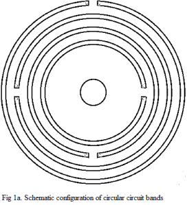
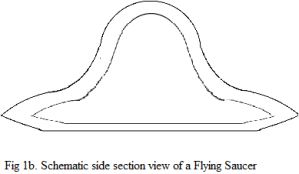
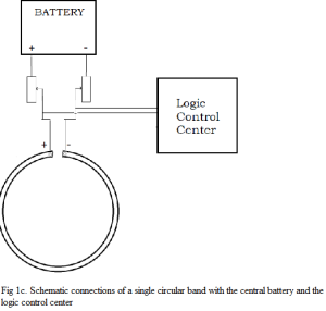
Figure 1 provides a schematic demonstration of the wiring configuration that might be used to generate the levitating force by ionizing the air under a Flying Saucer. Figure 1a is a schematic view of a viable configuration at the bottom of a Flying Saucer as illustrated in Figure 1b. Each circular band in Figure 1a is supposed to be made of highly conductive material so that it could be a circuit of low resistivity, when its two ends connect to the anode and cathode of a central battery through resistive devices (e.g. variable resistors) as shown in Figure 1c. All resistive devices connect to the logic control center which could adjust the resistive value of each device so that it could vary from 0 to ∞. In Figure 1c, if the resistive value of one device is ∞, while the other is < ∞, then the circular band would serve as a single electrode. If the resistive values of both devices are < ∞, then the circular band becomes a circuit of electrical current; especially, if both resistive values are 0, then the heat dissipation of the circuit band would be minimal, but the magnetic flux density induced by the current in that circuit band would become maximal. If the resistive values of both devices are ∞, then the circular band would become an insulated metal plate. Besides, the logic control center should be able to reverse the connections of a circuit band with the anode and cathode of the battery at any time. Furthermore, in the configuration of Figure 1a, the number of circular bands, the width of each band, and the gap between the bands could all vary. At the center of Figure 1a is a round metal plate that could serves as a single electrode (either an anode or a cathode) or a neutral pole, depending on how it is connected to the central battery.
With this viable configuration, if the battery could provide a high enough voltage, we could then create a glowing and hot plasma field below the Flying Saucer, which could be manipulated through the logic control center. In this way, we could create a controllable lift force so that the Flying Saucer could stay still in the middle of the air, or ascend and descend, slowly or rapidly, depending on how the logic control center manipulating the flow in the plasma field.
In addition to ionizing the air below the flat bottom of the Flying Saucer, we still need to ionize its horizontal surrounding air to generate the horizontal thrust, which could be accomplished by covering the inclined surface of the Flying Saucer with circuit bands as well. However, the circuit bands for generating horizontal forces cannot be in circular symmetry as those in Figure 1, but need to be more granular so that horizontally asymmetric forces can be generated.
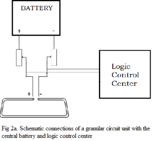
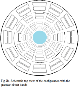
Figure 2 provides a schematic demonstration of the wiring configuration for the inclined side surface. Figure 2a shows the schematic connections of a granular circuit with both the central battery and the logic control center, which is basically the same as shown in Figure 1c for the connections of a single circular circuit. Figure 2b is a top view of the surface configuration with those granular circuits. The blue circle area in the center is not covered by the circuits for a reason that I will discuss a little later.
The Resultant Force
Once all the circuit bands on the surface of the Flying Saucer are used either to ionize the air or to impact the magnetic field in the air with their electrical currents, the air environment around the Flying Saucer will be turned into a very complicated magnetohydrodynamic field, accompanied by the vortices and shock waves induced by the movement of the Flying Saucer. The forces acting on every part of the surface of the Flying Saucer would add up together to form a vector of the resultant force, which will determine the acceleration of the vehicle, together with the action of gravity.
We do have the capacity of obtaining the information of how the maximum battery voltage, the manipulation of the logic control center, the speed and acceleration of the vehicle, the altitude, and the physical parameters of the atmospheric environment, etc would impact the magnitude and direction of the generated vector of resultant force acting on the vehicle. However, once a Flying Saucer goes up in the air, the pilot and the crew members do not have the chance to perform complicated magnetohydrodynamic calculations for the vehicle. What they could count on are only the readings from the meters and some simple operational mechanisms such as control wheel, various buttons, or maybe some kind of AR helmets, etc.
A critical task for the design engineers is to map all the complicated magnetohydrodynamic states for the combinations of the connection modes (i.e. which circuit band is connected as a electrode or a low resistance circuit or just a neutral plate, etc), obtained from numerical simulations and lab tests, onto some linear scales which could be represented by simple mechanisms like a thrust lever and a 3-D joystick as illustrated in Figure 3, through specially designed wiring.
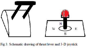
Although the actual magnitude of the resultant aerodynamic (i.e. the magnetohydrodynamic) force might depend on the real flying status and the atmospheric parameters, when the pilot pushes or pulls the thrust lever, the magnitude of the resultant force should increase or decrease in a linear way, or at least in a monotonic and roughly linear way. The 3-D joystick in Figure 3 comprises a stick that can be operated on the panel plane to control the horizontal moving direction, and a small ball that can be rotated around the axis fixed on the stick to control the vertical moving direction.
Because Flying Saucers do not have any heads and tails, they could move towards any of its radial directions; therefore, with the utilities like thrust lever & joystick, the pilot of a Flying Saucer is able to change the speed and the moving direction abruptly during the fly without making any turn or tilting its body, as often witnessed in UFO sightings.
The Energy Source
A powerful energy source is undoubtedly a critical component of a Flying Saucer because of the need to keep ionizing the proximal air. The solution for this need would naturally be a compact nuclear reactor, which is not only potent enough but also compact enough. Fortunately, reactors with those two characteristics were already available as early as 1950s when the first nuclear-powered submarine was built. Nowadays, the core size of a compact nuclear reactor could be as small as a hot tub or even a dustbin, while still capable of supplying the power for the total consumption of several small countries. Therefore, the feasibility of having a nuclear reactor which is suitable for a Flying Saucer is not a problem. However, although the size of the compact reactor could be very small, it is normally heavily shielded with a much bigger compartment on a submarine; the same would apply to any reactor used on a Flying Saucer for the sake of the safety of the crew members.
The best position on a Flying Saucer for a nuclear reactor would obviously be at the center of the lower part of the vehicle as shown in Figure 4, which is ideal for weight balance and wiring convenience since it is symmetric to every part of the shell plating, and is also good for internal space management since it can be separated from the working area by the shielding floor.
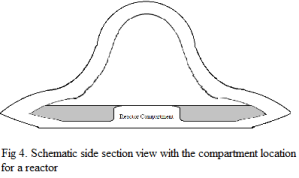
The strong residual radiation in either the landing sites or the crashing sites as mentioned in many of the Flying Saucer sighting reports could be an indication that the purported Flying Saucers might carry a reactor that is posited at the lower part of the vehicle just above the bottom skin. When a reactor-carrying Flying Saucer crashes, it would not be a surprise to detect a very strong radiation on the crashing site; however, if a strong radiation is detected on a landing site after the Flying Saucer safely took off, then it might imply some defects in the insulation of the bottom of the vehicle, which might result from a less than ideal quality of the layer of radiational insulation at the bottom for the reason that it is not directly connected to the working area, while the constant exposure to the high temperature of plasma could be tough to the surface of the bottom.
The Insulation
In addition to the insulation for nuclear radiation, there are another three major insulation concerns: 1) the strong magnetic field generated by the currents in the surface circuit bands and in the plasma; 2) the high temperature of the plasma; 3) the strong electrical field created by the electrodes of the central battery.
Correspondingly, the surface skin under the circuit bands as shown in Figures 1 & 2 should be built with electrical insulating material, and both the circuit bands and the surface skin should be fire resistant; behind the surface, of course, should be a layer of heat shield material to further reduce the temperature caused by the high temperature plasma; then there should be a layer of high magnetic permeability material (such as ferromagnetic metal) to shield the internal space from the strong external magnetic field, and to contribute to the structural strength as well; then another layer of heat shield material; and finally the internal wall should be made of electrical insulating material covered with heat shield paint. In addition to all that, of course, the compartment for the nuclear reactor needs to be shielded by high quality nuclear resistant material.
Furthermore, one tricky insulation concern is how to ensure that the internal circuit parts could be perfectly cut off when it is required so. For example, when the ends of a surface circuit band need to be disconnected from the electrodes of the battery (see Figure 1c and Figure 2a), we need to be sure that the previous connections are completely cut off. This becomes an issue because when the voltage between the anode and cathode of the battery gets extremely high, breakdowns of the normal insulators (e.g. air) in the internal connection circuit could happen as well. Therefore, special care should be taken for the insulation issue with the internal wiring.
Accordingly, the surface configuration of the circuit bands would be affected by how much voltage the insulators of the internal wiring can undertake. It would mainly affect the distance between the circuit bands which are used as opposite electrodes for breaking down the air, because the breakdown voltage of air increases as the thickness of air to be broken down increases. The good news is that we might find many materials of much higher breakdown voltages than air; but the bad news is that the distances between the internal wiring parts could be much smaller than the distances between the surface electrodes, which might impose a restriction upon the complexity of the surface configuration of the circuit bands.
The Onboard Radar, Ventilation, and Windows
Second to the nuclear reactor, onboard radar might be another major component of a practically functional Flying Saucer, no matter for normal navigation purposes or for military uses.
Unlike space ships, Flying Saucers that fly in the atmosphere should not count on carry-on oxygen bottles for the survival of the crew members; thus air ventilation is another important system for a Flying Saucer.
If allowed by the overall condition, some windows that enable the crew members to see outside the vehicle might be desirable, although with the onboard radar and other modern video monitoring equipment, the crew member should be able to navigate without any transparent windows.
The blue center in Figure 2b is particularly reserved for installing the onboard radar, ventilation outlets, and windows.
The G-Force Dissipating Seats
One common concern about any sudden change of movement status is that the resulting g-force might exceed the endurable limit of the best trained human beings. This concern has actually become one reason for some people to believe that the rapid Flying Saucers cannot be flown by humans. However, the g-force restriction on the crew members could be offset to certain degree by the size of the vehicle with the help of some special facilities which operate similar to the seatbelts we all wear on airplanes or in on-road motor vehicles, but with the whole seat attached to a retractable belt hanging down from the ceiling.
Within a large Flying Saucer, we might have fixed emergency positions for crew members. When the Saucer needs to make a quick change of movement status (such as quickly speeding up from a spot in the sky), the alarm will be sounded to alert that all crew members should run to the nearby emergency positions and buckle themselves up in the “belt-seats”, which are designed to dissipate the strongest g-force that could be generated by the Flying Saucer.
The Size
The size of the vehicle is a critical factor that might be easily overlooked by researchers for the feasibility study of building a Flying Saucer. According to the sighting reports, Flying Saucers are normally huge in size, which often puzzled the observers. However, the voluminousness could actually be a key to the success of building a practically operational Flying Saucer for the following reasons:
1) In order to dissipate the g-force, we need some free space for the “belt-seats” to be extended in all horizontal directions without colliding with each other, especially when the size of the crew is big, or with other parts of the vehicle.
2) The magnitude of the aerodynamic force upon a Flying Saucer generated from the magnetohydrodynamic field is obviously proportional to the size of the surface area of the Flying Saucer, which is in turn in proportion to the overall volume of the Saucer. Therefore, the aerodynamic force (or we might call it as magnetohydrodynamic force) per unit volume (i.e. the total force divided by the total volume) would roughly stay the same (in fact, it might increase) as the total volume of the vehicle increases.
On the other hand, the weight of all components (including human crew members) of the three dimensional object of the Flying Saucer is obviously not evenly distributed across the vehicle. Both the areal size and the thickness of the shell plating, which is not only responsible for the insulation as discussed earlier, but also responsible for the structural strength of the body, would increase in proportion to the overall volume of the vehicle. That might be the only part of the Flying Saucer which is of a roughly even distribution across the body. Some major components (such as the nuclear reactor, the onboard radar, etc) of the Flying Saucer with the average densities that are much higher than the average density of the whole Saucer would add concentrated loads only at certain locations, while most of the volume inside the shell is the empty space with some mobile objects (humans) moving around. As a result, the average weight per unit volume (i.e. the total weight divided by the total volume) would decrease as the overall volume of the vehicle increases.
Therefore, with a powerful enough energy source (the reactor-backed high voltage battery), the maximum aerodynamic force per unit weight would increase as the overall volume of the vehicle increases, which would enhance the mobility of the Flying Saucer within the limit of the allowed maximum voltage and the available energy supply.
3) One common basic characteristic of the reported Flying Saucers is their capacity of making extremely high g accelerations (e.g. sudden changes of direction, sudden accelerations from still to very high horizontal velocities), which means that a Flying Saucer needs to be able to create a thrust that is much greater than the lift force for supporting the vehicle to hover in the sky or to have a slow ascending motion. This would lead to a requirement that we should have the vertical projected area bigger than the horizontal bottom area.
However, the shape of a Flying Saucer needs to be like a flat saucer for two reasons: a) it will increase the horizontal stability since flat objects tend to stay in the level position during a free fall; b) it will decrease the horizontal resistant force (including the resistance from shock waves) when the vehicle moves horizontally. Therefore, in order to have a large vertical projected area for generating strong thrusts, we need to have an even larger horizontal bottom area. This indeed imposes a requirement on both the materials of the shell plating and the mechanism of generating the thrust: the increase of the weight of the shell plating should be way smaller than the increase of the thrust due to the increase of the vertical projected area.
But on the other hand, if we want to have a quick ascending movement of the Flying Saucer instead of hovering in the sky or slowly move up and down, then we would need a lifting power which should be even greater than the thrusting power since the vertical resistance would be undoubtedly greater than the horizontal one due to the flat shape of a saucer.
4) The larger the size of a Flying Saucer is, the smaller the relative impact of the dissipation of energy to the surrounding region would be.
5) Lastly, as mentioned earlier, the more compact the internal wiring circuit, the bigger the chance for the breakdown of the insulation materials between the opposite electrodes when the voltage gets extremely high. For this reason, we would prefer that the internal wiring be loosely laid out in relatively spacious places.
The Miscellany
Once the above discussed issues are taken care of, we would be pretty much able to build a functional Flying Saucer; however, there are still some more aspects that might be worth contemplating in order to have a better understanding of how we might practically build and use a Flying Saucer.
- The Air Boom Issues
There are two types of potential air booms. The first type would be caused by an extremely rapid expansion of air due to the sudden increase of air temperature after being ionized, in the same way as thunders are produced by lightning bolts. This type of air booms should be avoidable with a buffer in the wiring circuit to prevent an overly sudden increase of the voltage exerted on the surrounding air.
The second type of air booms might be a very tricky issue. Based on the classic teaching of aerodynamics, when an object moves faster than the speed of sound, it will generate sonic booms. However, sonic booms seem to have never been mentioned in Flying Saucer reports; instead, Flying Saucers are normally described as super swift but very quiet.
There might be several reasons for the possible disappearance of the sonic booms. First, unlike a sphere that is blunt all around, although the front of a Flying Saucer is blunt horizontally, it could be sharp vertically, which could help to improve the aerodynamic quality in terms of reducing the strength of shock waves.
Second, it has been known that plasma could greatly reduce the sonic booms. However, when a Flying Saucer move swiftly forward, the shock waves will be generated at its front, where we might not want to have plasma since it might pose a huge resistance force to the vehicle. But on the other hand, there will always be plasma at the bottom, and thus when the backward shock waves pass through the region under the bottom of the vehicle on their way to propagate towards the ground, they might be reduced to certain degree by the plasma field.
Third, the air surrounding the Flying Saucer would be extremely hot, so the shock waves would first travel through this hot zone and then enter the cold environmental atmosphere, which could cause the contour of the shock waves to curve inward.
Fourth, the steep gradients of both temperature and pressure from the proximal area of the Flying Saucer to a bit farther region would induce quite strong local wind, which would help to dissipate the shock waves.
Fifth, some auxiliary techniques (such as those applied to aircrafts) could also be used to further destroy the sonic booms created by the Flying Saucer.
- An Auxiliary Lift Force Implementation
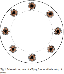
Although the capacity of ionizing the surrounding air is the most important advantage of a Flying Saucer over the conventional aircrafts, it does not mean that a Flying Saucer cannot make use of conventional approaches for the sake of saving energy when it is viable. For example, when a Flying Saucer hovers at a fixed position in the sky, it might not necessarily need to obtain the lift force by ionizing the air below the vehicle; instead, a setup as shown in Figure 5 might be used for this purpose in order to save energy and to avoid making glowing color around the vehicle. Figure 5 shows the top view of a Flying Saucer when its suspension in the sky is supported by a group of rotors. Obviously, when the generation of the plasma field is needed on the involved surface areas, all the holes that hold the rotors should be closed by sliding or folding doors on both the upper side and the lower side skin of the vehicle. Only when the rotors are needed, both ends of those holes can be opened to allow the rotors to operate.
Furthermore, not only air-dependent engines such as rotors or jet engines can be installed in the “brim” of the Flying Saucer, even rocket engines could be installed there as well, which will enable a Flying Saucer to come in and fly out of our atmosphere at will.
- The Electromagnetic Interference to the Surrounding Region
Once we realize that the glowing Flying Saucers are driven by the force generated from an extremely complicated magnetohydrodynamic field, we might no longer feel it difficult to understand the possible causes for the reported electronic dysfunctions when Flying Saucers came close. As shown in Figures 1 & 2, the surface bands that are used to generate the plasma field could also be turned into circuits to generate very strong electromagnetic field.
Actually, when Flying Saucers were reported to come close to certain on-road vehicles or radar stations, they were normally in the slow motion mode or even hovering at a fixed position in the sky, which means that they did not need a strong thrust from the plasma field besides the lift force. In that case, they could leverage a huge electric power to generate a strong magnetic field in the nearby region which could cause the electronic apparatus to dysfunction.
- The Possible Spinning Mode
In some Flying Saucer sighting reports, it was said that the Flying Saucers were spinning when coming closer to the witnesses. Obviously, the spinning movement would consume extra energy with no obvious benefit except for entertaining effect, and thus it could have very possibly been the imagination of the reporters.
However, considering the fact that the generation of either the lift or the thrust on a Flying Saucer by the plasma flow would always incur enormous heat dissipation to the surrounding atmosphere, it might not be so obvious whether the purported spinning motion could serve some dynamic purpose until detailed numerical simulations are conducted.
- The Possible Magnetic Shielding
It is not a surprise if we are told that a very strong magnetohydrodynamic field could disturb the radar wave that is electromagnetic in nature, which could be the main reason why it has been often reported that when some people could see the Flying Saucers with their eyes, those sitting in front of the radar screens could not see them (this might be a good reason for a Flying Saucer to have transparent windows).
Besides, the possibility of deflecting the approaching projectiles by the electromagnetic field, as sometimes reported in the past, might not be completely ignorable, depending on how strong the field could be.
In fact, with a nuclear reactor aboard, the Flying Saucer owner could do a lot things, even including installing a laser weapon.
- The Air Levitating Power
Of course, the fundamental concern for building a Flying Saucer is the feasibility of levitating a heavy vehicle without using rotor blades or jet engines. Here is a rough idea about the power of air pressure: the normal atmosphere could exert a pressure of greater than 10 ton on every square meter area. Thus, if we could double the air pressure below the bottom of the Flying Saucer through ionization, then we will have approximately 10 ton extra pressure on every square meter area at the bottom of the Flying Saucer, after cancelling out the normal atmosphere pressure exerted on the upper side of the vehicle. In that case, if the radius of the Flying Saucer is 40 meters (which is quite small for a Flying Saucer since it is often reported that a Flying Saucer is of hundreds of meters in diameter), then we could have a upward force at the bottom to lift a ship of more than 5000 ton. Even without the need to have illustrated distributions of flow parameters in the actual complicated magnetohydrodynamic field, based on our known physical principle, it is very clear that when the horizontal surface area is large enough and the voltage is high enough, especially for the shape of a round plate, we would be able to levitate the object with the ionized plasma.
- Travelling by Flying Saucer in the Future
A very moderate prediction about the near future of the aviation industry can be made that in the coming decades, once the principles of building Flying Saucers become known to private or public (as long as non-government) manufacturers, travelling by Flying Saucer will become a new fashion in the world, especially for intercontinental travels.
In fact, Flying Saucers do have an advantage for intercontinental flights over any existing means for doing so because it can ascend and descend vertically, which is in turn determined by two basic features of a Flying Saucer: 1) it can keep its level position all the way from ascending, orbiting, to descending and landing; 2) it can be very flexible in terms of using propulsion means. Considering that it is on the order of an hour or two for a low earth orbital object to complete a full circle around the earth, and the ascending or descending time is pretty much the same all around the world, theoretically, the difference between going two places in the world could be within the order of an hour, and practically it could be much shorter.
Moreover, for the sake of intercontinental transportation, a Flying Saucer does not need to fly by magnetohydrodynamic force as discussed in this article (and thus no need to have a nuclear reactor onboard). It can use a mechanism that would allow shifting the propulsion system from conventional air-dependent engines (rotors or jet engines) to rockets.
Accordingly, the philosophy behind its ascending plan would be very different from all the existing sub-orbital transportation means. Since it can use the conventional propulsion (not to mention plasma propulsion) before it reaches the boundary of the atmosphere, the so-called Kármán line, it needs not to rush up during the ascending phase, and then it can use propulsion for most part of its orbiting (normally within 30 minutes) right beyond the boundary of the atmosphere, or even within the Mesosphere layer but close to the boundary of the atmosphere, since it will not cost much fuel to maintain a horizontal cruise there because the air drag is already very low.
As a matter of fact, nowadays jet engine airplanes would also fly in the Stratosphere, and thus the extra height for getting to the Mesosphere or its outer boundary is not that big, but in a much lower air density environment.
For a moderate average ascending speed of 90 miles per hour (with a plan that is slower within the Troposphere where the air density is high, and faster within the Stratosphere and the Mesosphere where the air density is low), which would cause only a few thousandth of extra g force, the ascending could be accomplished within half an hour; similarly, the descending could be within an hour and a half (for the sake of the health of ordinary passengers), and then the difference between flying from New York to London and from New York to Beijing would be within minutes instead of hours.
For irregular fights within the atmosphere, especially for military purposes, the fastest and also most efficient way, is to make use the forces generated from the plasma field as discussed in this article.
Conclusion and Final Remarks
This article is obviously not a scientific discovery paper, since none of the knowledge involved in this article is new, but could all be found as popular science from the internet without bothering to delve into academic literatures. Nonetheless, people who are interested in the possibility of building a Flying Saucer could get from this article not only a rough idea of how it could be done but also what might be involved to do so. Therefore, this article could serve as a general feasibility report on whether humans are capable of building a Flying Saucer that could act like many of the reported UFOs.
One clear conclusion that we might draw here is that humans should have been able to build a so-called alien-style Flying Saucer, even decades ago!
The reason for us to be ascertained that humans were able to build Flying Saucers even decades ago is because three most important required technological elements were all available to humans around the end of 1960s, which are plasma technology, large scale numerical simulation and wind tunnel testing, portable nuclear reactor. With nowadays big-data based AI technology and supercomputing capacity, as well as many other high-tech abilities, we can certainly do much better; but even without these high-tech advantages, humans should still have been able to build a Flying Saucer several decades ago!
Based on this conclusion, it is very naturally to ask, “Have humans already built Flying Saucers?” In order to answer this question, we might ask ourselves another question: “Would humans have the intention to build a Flying Saucer?” If we can agree on a positive answer to this question and we know humans do have mastered the necessary knowledge and technologies for doing so, then it might be easier for us to imagine that some of the reported Flying Saucers could have actually been steered by humans.
Obviously, whether UFOs are all driven by aliens has long become a social philosophical and psychological issue instead of a technological issue. Accordingly, this article is definitely more of a philosophical paper than a technological dissertation. The purpose is not to instruct readers to build a practical Flying Saucer, but to change the public mindset concerning the Flying Saucer related myth. Nonetheless, efforts are also made in this article to present the most important aspects of building a Flying Saucer in a clear and definitive way, because that is the only way to convince the audience that we do have the ability to build Flying Saucers, before they could actually see a real manmade Flying Saucer.
Considering that a real manmade Flying Saucer would be the best testimony to end the fancy myth that only aliens can build the swift glowing Flying Saucers, it might be worth a few words about the general perspective of a project to build a Flying Saucer. For a project which does not have a clear (openly known) precedent example to follow, it will be very reasonable for any investor who would be interested in building a Flying Saucer to intertwine the team buildup, the fund allocation, and the preliminary engineering study together in a step by step fashion, until he feels ascertained about the final success of the project. Naturally, the first step would be to do numerical simulations to investigate the magnetohydrodynamic field with some simple configurations of surface circuit bands as proposed in this article. The critical factor of size as discussed earlier in this article gives numerical simulations an advantage over lab tests since lab testing would usually start with small sizes. Once the numerical simulations could provide the complicated flow field diagrams of velocity, temperature, and pressure distributions in the magnetohydrodynamic field, lab testing can start, which will provide more realistic data than simulation results for the real engineering design. Of course, a full size team buildup and budgeting would also start before the real engineering design once the investor feels comfortable with the numerical and lab results.
As a writing that is meant to be a social philosophical reading based on the popular science, this article has been written with minimal technological jargons unless necessary, so that it could be as comprehensible as possible to the general public. Furthermore, this article does not list any technical reference because no need of digging into the issue more than reading the article itself is expected for comprehending why Flying Saucers can be made by humans.
However, the language in the style of popular science might potentially be challenged by those who love professional jargons and critically prefer technical curves of testing or computational data. But unfortunately, one common element in the UFO related pop culture around the world is the purported government-cover-ups. The main reason for this buzz word to become popular should be that we cannot actually find any government document from any country to tell us how much the world officials have been involved in building Flying Saucers, which also causes it impossible for anyone from the general public to provide practical data of real Flying Saucers that might have been possibly built in history.
But on the other hand, the general public around the world might have accesses to all kinds of potentially acquirable information, and thus would become the most reliable panel for judging the viability of any design ideas. Accordingly, once the idea of how to build a practical Flying Saucer is known to the public, then it will be left for the open public with all kinds of backgrounds to judge whether they could trust the feasibility of the presented idea. This would indeed make it even more important that whoever intends to discuss the feasibility of building a Flying Saucer should make it not only as practically viable as possible in a clear and definite way, but also present it in an as common as possible language, which has been an important guiding philosophy for writing this article.
Reference
Since all knowledge involved in this article has become part of the popular science for decades, no need of digging into the issue more than reading the article itself is expected for comprehending why Flying Saucers can be made by humans, and thus this article does not list any technical reference.
Figure Captions
Fig 1a. Schematic configuration of circular circuit bands
Fig 1b. Schematic side section view of a Flying Saucer
Fig 1c. Schematic connections of a single circular band with the central battery and the logic control center
Fig 2a. Schematic connections of a granular circuit unit with the central battery and logic control center
Fig 2b. Schematic top view of the configuration with the granular circuit bands
Fig 3. Schematic drawing of thrust lever and 3-D joystick
Fig 4. Schematic side section view with the compartment location for a reactor
Fig 5. Schematic top view of a Flying Saucer with the setup of rotors

While many signs have shown that getting thrust from ionization of air has been used in some flying saucers (e.g. in the Falcon Lake incident) since long ago, generating thrust for flying saucer through external ionization of air might not have significant environmental impact in the near future due to the very limited number of flying saucers that could be possibly built in the near future. However, humans should be very careful about the idea of getting propulsion through ionizing air due to the environmentally detrimental end products of the ionization which are nitrogen oxides. Especially, humans should strictly refrain from using internal ionization of air as apparently used by the flying saucer in the Falcon Lake incident to build propulsion systems for conventional public transportation flying craft; otherwise, it could be doomsday disaster for the whole mankind.
LikeLike